Protection aim 3: Basic principles
Function maintenance for safety-relevant electrical systems

If there is a fire, escape and rescue routes must remain usable and important technical equipment, such as emergency lighting, fire alarm systems and smoke extraction systems, must continue to function. In addition, certain technical systems must support the fire brigades in fighting fires for a sufficiently long period of time. To guarantee the power supply and thus the function maintenance for these technical equipment and systems if there is a fire, the appropriate installations must be equipped with special cables and routing systems.
Technical equipment with function maintenance is required for the following buildings and areas: Hospitals, hotels, restaurants, tower blocks, meeting places, shops, closed indoor car parks, metro systems, the chemical industry, power stations and tunnels. These buildings are frequently visited by large numbers of people, creating an increased safety risk for gatherings of people. However, with certain systems, property and the environment must also be protected. The requirement for electrical installations with function maintenance is a component part of the construction regulations. Function maintenance only relates to those areas which provide the power supply to safety-relevant electrical systems, such as emergency lighting, alarm systems, fire alarm systems, automatic extinguishing systems, smoke extraction systems, etc. Here, the regulations require that the power supply must be guaranteed for a specific period of time, even if there is a fire.
30 minutes: Function maintenance for rescue and a safe evacuation
The first 30 minutes after the start of a fire play an important role when clearing the affected building. During this time, function maintenance must be guaranteed for the following units:
- Safety lighting systems
- Lifts with fire control
- Fire alarm systems
- Alarm systems and systems for issuing instructions
- Smoke extraction systems
60/90 minutes: Function maintenance for effective firefighting and difficult evacuation
To support firefighting operations, it is imperative that certain technical equipment is supplied with sufficient power for 60 or 90 minutes after a fire breaks out in a building.
This equipment includes:
- Automatic extinguishing systems
- Water pressure increase systems for fire water supply
- Mechanical smoke extraction systems and smoke protection pressure systems
- Fire brigade lifts
- Bed lifts in hospitals and similar equipment
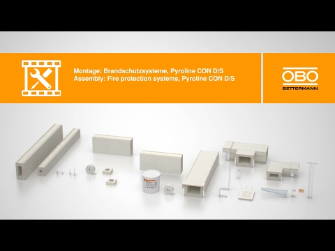
A cable system with integrated function maintenance is, according to DIN 4102 Part 12, the combination of the routing system (cable ladder, cable tray, fire protection duct, etc.) and cables. The proof of the function maintenance of electrical installation material must be obtained by a fire test, carried out by an independent materials' testing agency.
The test body, i.e. the cable system, must have a testing length of at least 3,000 mm and is installed in a special oven. The cables are routed on the support systems. The test criterion is: No failure of the cables through short-circuits or conductor breaks through the required testing time.
If there is a fire, the cables and conductors are subjected to extreme loads from flames and heat. Nevertheless, cables used for a safety installation must be able to withstand temperatures of up to 1,000 °C and higher for a specific period of time, without there being a short-circuit of the copper conductors. As the copper conductor may begin to anneal at these extreme temperatures, thus impairing its own mechanical stability, the support system serving as a "support corset" has a special significance. Due to the temperature development in the cable, in the case of cables with integrated function maintenance, the insulation has a special role to play. There are two construction types: The cables possess a special winding around the copper conductor made of glass silk or mica tape. If there is a fire, then the cable insulation burns completely, creating a layer of ash. This is kept together by the windings and ensures that the copper conductors are kept apart and that no short-circuit of the support system can take place. More modern cable types use special ceramising plastic insulation instead of the coils. The main component of the insulation is aluminium hydroxide, which forms a soft ceramic sleeve when it burns. This creates the desired insulation of the wires carrying current, both between each other and naturally also to the support system.


After erection, each cable system must be permanently labelled with a sign. This labelling must contain the following information:
- Name of the erection engineer of the cable system (installation engineer)
- Function maintenance class "E" or "P"
- Test certificate number
- Owner of the test certificate
- Year of manufacture
Cable systems according to DIN 4102 Part 12 also include cable ducts. The different construction types of the ducts must ensure that the cables routed in the interior continue to function in a fire on the outside. This is ensured using different duct materials. Therefore, no special function maintenance cables need be routed in fire protection ducts. It is possible to use normal, PVC-insulated cables, tested according to the standard. As cables with integrated function maintenance are usually created with a nominal voltage of 0.6/1 kV, there are no options in the field of cable systems for routing medium-voltage cables with function maintenance, for example. However, these cable types can be routed in the fire protection duct, achieving the protection aim of the safe supply of a safety-relevant system.


For function maintenance, the support structures are not defined exactly in the approvals of the fire protection ducts. With these mounting variants, it must be ensured that the ducts do not slide off the support systems. Pendulum suspensions or suspended support-bracket combinations with additional threaded rod locking at the bracket tip were proven in the fire tests for electrical function maintenance, so that these have proven their worth in practice, also for the suspension of fire protection ducts.
There are various routing options for routing cables with integrated function maintenance. Besides the type and number of cables to be routed, economic aspects are naturally also of importance. There are many variations, from the tried and trusted standard support structures with which planning is possible, irrespective of the cable type, right through to economical, cable-specific solutions.

The standard specifies that not just the cables themselves belong to the function maintenance of an electrical cabling system but also the routing systems. With standard support structures, it is possible to select the cables required for the installation freely. This is possible, as all the cable manufacturers have proved the function maintenance of their safety cables for the standard support systems.
DIN 4102 Part 12 defines three standard routing systems:
- Routing on cable ladders
- Routing on cable trays
- Individual cable routing under the ceiling
The individual clips or profile rails and clamp clips, with and without long troughs, belong to the individual routing of the cables under the ceiling defined in test standard DIN 4102 Part 12.
The parameters of the horizontal routing types were transferred to vertical installations, making the use of vertical sections possible.
Benefits of standard support structures
- Free cable selection, as the combinations of cables and standard support structures possess proof of applicability.
- No binding to specific cable types.
- The structures are ideal for smaller projects.
- Testing means that the countless installation variants are approved for many years.
Advantages of cable-specific routing types

- Low material and mounting costs
- Planned systems: Support systems are clearly assigned to defined cable types.
- Large selection of approved cable types
- Ideal for larger buildings (project business)
The following cable-specific support systems can be considered for an economical electrical installation with function maintenance: Cable trays with and without threaded rod lock, mesh cable trays, cable ladders, individual clips, grouped supports and pressure clips. Even electrical installation pipes in proven variants can be mounted.
When selecting the products approved for function maintenance, observe the specifications of the planner and the details of the test certificates. All the parameters on mounting and the usable components must be taken from the test certificates. The systems were tested at German testing institutes in cooperation with renowned manufacturers of safety cables (Dätwyler Cables, Kabelwerk Eupen, Leoni Studer, Nexans and Prysmian). In addition, certain routing types were tested and approved appropriately at local testing offices along with cable manufacturers from other countries according to DIN 4102 Part 12.
The following cable-specific support structures and routing types are available:
- RKSM cable trays
- GRM and G-GRM mesh cable trays
- LKM cable routing ducts
- SL cable ladders
- Tunnel systems made of VA
Many combinations with cable spacing clips and clamp clips with larger fastening spacing distances were tested and proven through various cable manufacturers. Even the routing of function maintenance cables in pipes was covered. To obtain a clear overview, OBO compiles a so-called cable list with the tested and approval routing system and cable combinations available at regular intervals.


Junction boxes of the FireBox series are available for connecting and branching safety cables. These are equipped with a high temperature-resistant connection unit with ceramic terminals and offer terminal areas of 0.5 mm² to 16 mm² of copper cross-section. The T series FireBoxes possesses all the benefits of thermoplastic cable junction boxes. These include the high IP protection rating of maximum IP66 and the maximum impact resistance of IK10 and a high resistance to breakage. Boxes with soft plug-in seals or closed variants are available. Here, the cable glands can be located freely. Fastening either takes place on the outer straps or through the box base with fire protection screw ties. The high temperature-resistant terminals are pre-mounted on the connection unit. The protective conductor terminal is connected to the support clamp, meaning that covers of the metal parts are not required. The FireBox is tested and approved as a connection socket for electrical function maintenance to DIN 4102 Part 12 with the classes E30, E60 and E90. A separate fuse holder allows protection of a branch.
Cables on rising sections must be effectively supported in the transition area between vertical and horizontal routing, to prevent bending or sliding. Continuous cable systems only receive the appropriate function maintenance classification when there is effective support at a spacing of max. 3.5 m.


The boxes, made of a non-combustible material with integrated mineral fibre insulation and which are mounted directly over a series of clips, have proven their worth as a practical solution. This allows avoidance of the difficult loops according to DIN 4102 Part 12. The action principle is similar to that of the cable insulation in the storey ceiling: If there is a fire, the series of clips in the box remains relatively cold and the cables remain clamped, effectively preventing breaking. This means that DIN-conformant and effective support of the vertically installed function maintenance cables can be achieved in a way which is extremely economic and space-saving.

Of equal importance to the selection of the cable support system is the decision for the most suitable fastening system. Here, too, the individual factors on the construction site must be taken into account. Depending on the substrate, many different anchoring systems are available with fire protection suitability.
For system fastening, the approvals of the cable systems with integrated function maintenance according to DIN 4102 Part 12 require metal anchors with a general construction approval or a European Technical Approval/Evaluation. In contrast to normal "cold" fastening, these anchors must be set at least twice as deeply for a fire protection application. Alternatively, anchors are used which have proven their load capacity and fire resistance length in a fire test. With these solutions, the necessary setting depths according to the load are listed in the approval documents or in the appropriate fire protection reports. It must also be noted for which substrates and resistance classes the anchors are approved.
The most important solutions for anchoring small to very large loads in most substrates are:
- Metal spreading anchors for use in concrete:
Heavy-duty ties, nail ties, interior thread anchors, cavity ceiling ties - Injection ties for use in concrete, hollow brick and porous concrete:
Anchor rods inserted in plastic or metal sieve sleeves with special mortar - Bolt ties for use in concrete and various types of masonry:
Self-tapping concrete screws with various head shapes - Wood screws with a large embedment depth

Wood is a combustible material and, as with steel constructions, wooden components are firstly only suitable under certain conditions for the fastening of fire-tested electrical installations. Coatings and panelling are also used in the constructions, in order to achieve a fire resistance class at all. However, if there is a fire, wood has a very good property: When burning, an insulated layer is created which delays further combustion. The wooden component must be dimensioned in such a way that failure cannot occur at an early stage. Taking the combustion rates into account, various cable support systems for electrical safety systems with the function maintenance classes E30 and E60 can be fastened to wooden components. Wood screws with a suitable steel cross-section and sufficient embedment depth are used for fastening. The long screws drill deep into the cross-section of the wooden beam, ensuring a secure hold of the mounted support systems, despite burning. Various mounting variants are documented in a fire protection survey.

Tutorials on the subject of function maintenance
Simply explained, comprehensively protected. Our tutorials explain exactly what is important with the second protection aim.