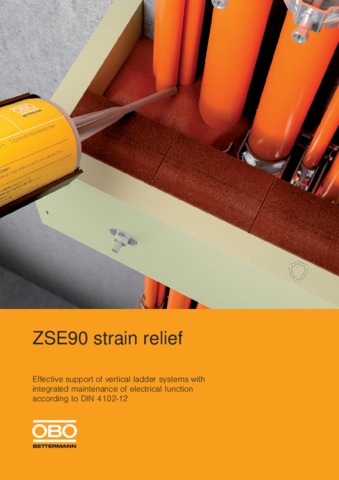
ZSE90 strain relief
Effective support of vertical cable systems with integrated maintenance of electrical function
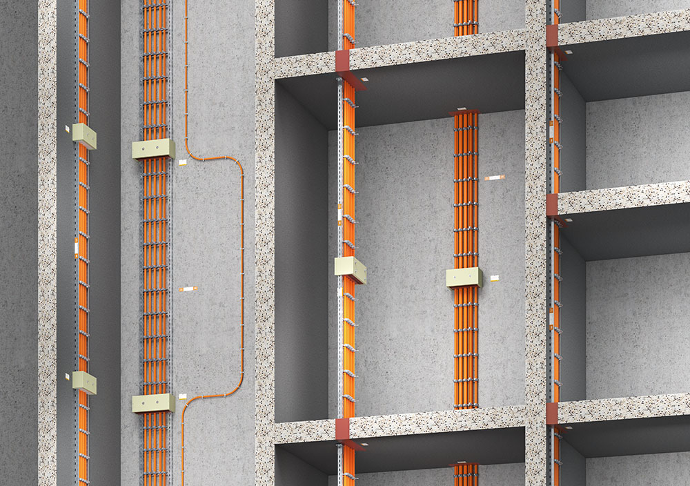
Maintenance of electrical function is one of three protection aims in the event of fire and is required in all buildings in which large numbers of people meet. The maintenance of electrical function exists when the current flow is not interrupted during a fire, thus allowing key electrical systems, such as emergency lighting, ventilation and fire alarm systems, to continue working. If all the cables for the maintenance of electrical function are continually routed in a vertical direction, special measures must be taken to prevent an interruption of the electrical circuit in the event of fire. This is because, with this method of routing, a direct fire load in the area of the clips can mean that the cables are no longer clamped as required and can tear due to their dead weight.
In order to prevent this happening and to maintain secure functioning of the electrical supply, norm DIN 4102 Part 12 requires an effective support of the cables at a maximum distance of 3.5 metres.
Options for the effective support through strain relief
Basically, there are three options for the effective support of vertically routed cables for the maintenance of electrical function, which comprise the creation of strain relief to prevent the cables from tearing.
Strain relief through loops
If the cables are routed in loops, if there is a fire the cables deposit themselves on the sides of the horizontal clip elements on their forming ash layer. This prevents tearing through the weight of the copper.
However, a major disadvantage of this type of strain relief is the the large space requirement at the side and the complex routing whilst maintaining the bend radii. For example, this variant cannot really be implemented in a fully assigned vertical shaft.
Strain relief through cable insulation
An additional strain relief variant is the installation of approved cable insulations in the ceiling openings.
If there is a fire, the copper weight is caught by the series of clips located directly above the floor. The series of clips remains cold due to the function of the insulation.
For strain relief through cable insulation, the storey height may not exceed 3.5 m.
The OBO solution for strain relief: ZSE90
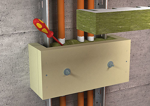
The most effective strain relief solution has been shown to be housings made of non-combustible material with integrated insulation. These are mounted directly over a clip row, meaning that the complex loops can also be avoided for storey heights of over 3.5 metres. The action principle is similar to that of the cable insulation in the storey ceiling: If there is a fire, the series of clips in the housing remains relatively cold and the cables remain clamped, effectively preventing breaking.
The OBO ZSE90 strain relief can offer such a recognised fire protection solution. With the ZSE90, DIN-conformant and effective support of the vertically installed cables that maintain the electrical supply can be achieved in a way which is economic and space-saving.
Various housing variants offer strain relief for each installation
The housing of the ZSE90 strain reliefs, in conjunction with the appropriate insulation, prevents a direct fire load at the clips in the event of a fire. The housings are delivered pre-mounted in the appropriate widths, heights and depths.
For installations in small places, they can also be adapted and shortened individually at the mounting location.
The ZSE90 strain relief can be used for all widths of rising ladders, for vertical single clip installations as well as cable installations on profile rails.
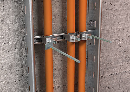
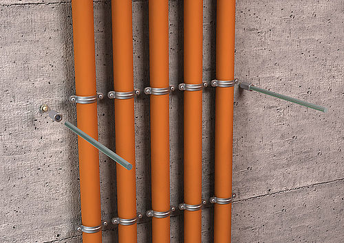
The supplied mounting sets which are included allow two different types of fastenings.
Directly on the wall next to the cables or with threaded rods and slide nuts in the rungs.
3 variants of the ZSE90 for the safe maintenance of the electrical function
The ZSE90 strain relief from OBO is available in three different versions and is approved for all classes ensuring the maintenance of electrical function from E30 to E90 in combination with standard support structures.
The three versions at a glance:
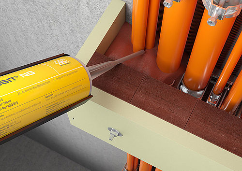
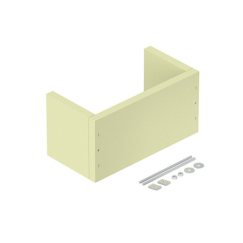
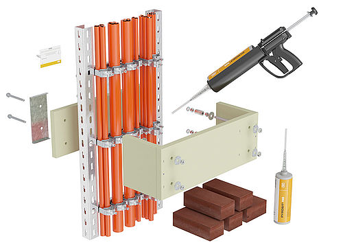
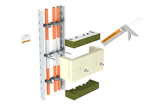
• The flexible solution: ZSE90 for direct wall mounting with foam filling
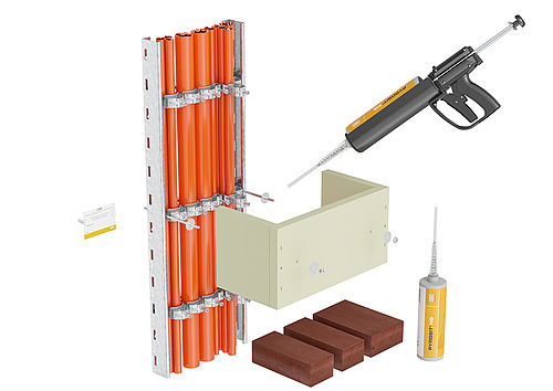
In this variant, the non-combustible, three-sided housing of the ZSE90 is filled with insulation made of foams:
The areas not assigned with cables are filled with the PYROPLUG® Block foam blocks. The spaces next to, between and behind the cables are filled with the PYROSIT® NG fire protection foam.
Thanks to the filling tip of the PYROSIT® NG cartridge, the smallest gaps can be reached easily. The amount of material required to fill the housing is dependent on the individual cable assignment. This means that you can choose in a completely flexible manner which volume of which insulation material is required for your installation.
• The extraordinary strain relief: ZSE90 for mounting on suspended rising routes with foam filling
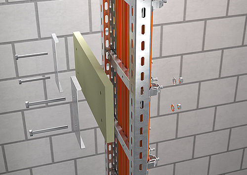
It is now possible to erect vertical ladders with a gap to the wall in systems with the maintenance of electrical function to DIN 4102 Part 12.
Strain relief to prevent the cables from tearing during a fire must still be created. Here, a further variant of the ZSE90 comes into play: namely, the four-sided variant of the strain relief.
The strain relief consists of a U-shaped housing, a matching lock plate made from the same non-combustible material and a mounting set for the installation on vertical ladders consisting of U profiles. In this variant too, the filling takes place using PYROPLUG® Block foam blocks and the PYROSIT® NG fire protection foam Foam filling
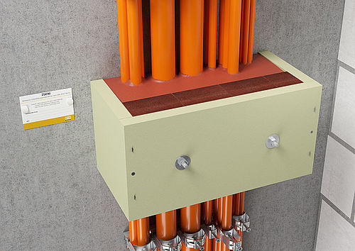
• The tried-and-trusted variant: ZSE90 for direct wall mounting with mineral filling
In the tried-and-trusted variant for direct wall mounting with mineral wool filling, the housing of the ZSE90 is filled with mineral fibre plates and wool with a melting point of over 1,000 °C.
This solution is particularly suitable for small cable assignments. Mounting is not complicated: Before the housing is mounted, the cables are coated with the thermally insulating PYROCOAT® ASX ablation coating.
When the housing has been attached, the mineral fibre plates are adjusted to the existing insulation and then the residual joints around the cables are also filled with the PYROCOAT® ASX and the surface of the plates in the housing are sealed. In order to achieve a secure function, the dry layer thickness must be 1 mm.